Monday, 16 August 2021

Monday, 9 August 2021

Friday, 16 July 2021

Sedimentary Way Up Structure- Part-Final


WAY-UP STRUCTURES: PART-FINAL


        way up the structureway up criterion, or geo-petal indicator is a characteristic relationship observed in sedimentary or volcanic rock, or sequence of rocks, that makes it possible to determine whether they are the right way up (i.e. in the attitude in which they were originally deposited, also known as "stratigraphic up" or "younging upwards") or have been overturned by subsequent deformation. This technique is particularly important in areas affected by thrusting and where there is a lack of other indications of the relative ages of beds within the sequence, such as in the Precambrian where fossils are rare.


A complete pdf is kept in the link mentioned below:

Link: Sedimentology > Sedimentary Structures > Way Up Structures 


Find me on my other social media platforms:

INSTAGRAM: https://www.instagram.com/confident_learning/?hl=en

TELEGRAM: https://t.me/Confident_Learning

BLOG: https://confidentlearning.blogspot.com/2021/05/Aspirants-JAM-GATE-GEOLOGY.html

E-MAIL: mk.confidentlearning@gmail.com

Website: www.rfhi.in

Sunday, 11 July 2021

Sedimentary Way Up Structure- Part 2


WAY-UP STRUCTURES: PART-2


1.1.1   Crossbedding

Cross-bedding is a series of laminations included within a larger sedimentary bed. A directional current allows the laminations to build upon the leeward (downstream) side of a migrating bedform called a ripple. (Bigger versions of ripples are called dunes, and they create cross-beds as they migrate, too.) Ripples and dunes form in a directional current of either water or air. They accumulate at the angle of repose for that size of the sedimentary particle, and within that medium (saltwater, freshwater, or air). In general, it is a gentle angle of around 30° of dip.

In terms of shape, cross-bedding is most useful when the cross-beds show a pronounced concavity, with the scoop shape curving upward, like a smiley face. This concave-up shape is a reflection of the cross-beds curving into a gentler orientation, approaching parallel to the base of the main bed.  We call this “tangential,” from the geometric term describing a line intersecting a circle at one point. At the top of the bed, in contrast, they are often truncated (“stopped short” or “cut off”), because the original upper tangential portion of the leeward side of the ripple has evidently been “planed off” by post-depositional erosion.

A sketch showing how cross-beds approach parallel with the main bed's bottom but at the top of the bed, erosion has removed the tangential portion, resulting in a truncated contact (Figure 8). Another way of putting this is that the angle between the crossbred and the main bed is typically small at the bottom (close to parallel) and larger (around 32 degrees or so in dry sand) at the top.

Figure 8: A cartoon showing the different cross-bed/bed relationships at the upper and lower portion of the bed.

This leads to important insights, as shown in the case study of the Mixed-Up Quartzites of Cape Agulhas.

Example 0X: Examine this panorama of a specimen of cross-bedded red sandstone (Figure 9). There are two halves to the sample shown. One is right-side-up. The other is up-side-down. Explore the two samples to see if you can figure out which one is which, applying the criteria explained above.

Figure 9: Specimen of cross-bedded red sandstone.

Really large cross-beds form via aeolian (wind) deposition in dune fields. The shape and geopetal implications are the same, but the cross-beds are much larger. Here is an example (right-way-up) from coastal exposures in the western Orkney Islands:


Figure 10: Cross bedding exposures in the western Orkney Islands


MAGIC BOX è Exceptions to the Rule

Cross-bedding can be tricky. Sometimes cross-bed laminae accumulate without the tangential, concave-up portion, and sometimes they preserve the upper convex-up portion at the ripple crest. Even crazier, sometimes they accumulate not on the leeward side of a dune, but the upstream (stoss) side! Let us take a moment to see what these complications look like

1.1.2   CLIMBING RIPPLES

Image (Figure 11) showing annotation of a photograph of climbing ripples in sandstone. A Swiss Army knife serves as a sense of scale. The climbing ripples' foresets (leeward side laminae) build up and to the left, implying current flow from the right toward the left.


Figure 11: Climbing ripples in cross-sectional view, Morrison Formation, Greybull, Wyoming.

Climbing ripples form when downstream migration of a ripple or dune is accompanied by rapid vertical aggradation of sediment. This tends to occur when the sedimentary load is higher than the capacity of the current that’s carrying it. Climbing ripples are distinct structures indicating critical to supercritical flow, but they often look about the same right-side-up as they do up-side-down. The concave-up portion of the laminae in the lee of the ripple is matched by the convex-up crest of the ripple itself, buried as soon as it forms. As a result, they can mislead the historical geologist.

 Consider the example in Figure 12; if you flipped the photo up-side-down, it would be difficult to tell:

The image is shown in Figure 13 shows a cross-section through three sets of climbing ripples from modern (unlithified) sand deposits in the Mississippi Delta region of Louisiana. Note how the largest, oldest, deepest set of cross-beds shows an undulating set of internal laminations, and these “climb” up and to the right, with tangential bases. This is likely indicative of supercritical flow. The the second set has a trough-like bottom that cuts into the older set of cross-beds, and is truncated by the most recent, uppermost, thinnest set of cross-beds.


Figure 12: Photograph showing two sets of climbing ripples between planar laminated beds. The field of view is about 30 cm by 20 cm, and a lens cap serves as a sense of scale. The climbing ripples' foresets (leeward side laminae) build-up and to the left.


Figure 13: Photograph of a cross-section of modern sand deposits. The vertical trench wall shows three sets of climbing ripples, with the cross-bed sets climbing up and to the right.


TO BE CONTINUE....

Saturday, 10 July 2021

Sedimentary Way Up Structure - Part 1


WAY-UP STRUCTURES : PART-1

Introduction

“Which way’s up?” With rocks, the answer is not always clear.

If layered rocks have experienced mountain building, they may be rotated from their original horizontal positions into vertical orientations, potentially confusing geologists, since the principle of superposition no longer applies.

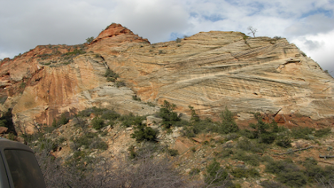
Consider the hypothetical example illustrated in the Figure 1: you discover a vertical sequence of strata. In one layer, you find evidence of a mass extinction event. In another layer, you find evidence of glaciation. Did an ice age cause the extinction? Or did the extinction somehow trigger the ice age? In order to pose intelligent questions about causality, you need to know which one is older. The older event can influence the more recent event, but not the other way around.


Figure 1: An exciting outcrop: but in order to interpret it correctly, we need to know which strata are older, and which are younger.

Even more extreme is when compressive stresses associated with convergent plate tectonic settings manage to fold beds into up-side-down positions. If the beds are up-side-down in such a tectonic inversion, it could really throw off the interpretations of the Historical Geologist: they would be reading Earth history backward!

In such situations, we need reliable tools in order to accurately interpret which direction was “up” when the rock originally formed. We call these patterns that look different right-side-up compared to up-side-down by the general term “way-up structures.” Some geologists also call them “geo-petal structures.”

Way-up indicators are critical for figuring out the correct sequence of geologic units. The help us determine “younging direction,” the direction in which strata get younger. (This is the same as paleo-“up” or “facing direction.”)

The welter of terminology shouldn’t turn us off: it’s an indication that geologists put a strong emphasis on finding and relying on way-up structures. Consider this example (Figure 2):


Figure 2: Geopetal structures that point in the paleo-“up” direction (red arrows) are of critical value in deciphering the story told by a sequence of strata.

Three layers are shown in outcrop at Earth’s surface, color-coded green, blue, and yellow. They are folded into what appears to be a series of anticlines and synclines. Given superposition alone, we would assume the lowest one is oldest, and the uppermost one is youngest. However, way-up structures in these three units point downward as the “up” or younging direction. Therefore, the exposed layers are part of a larger-scale fold, and the upper (upright) portion of that fold has been removed by the forces of erosion. Without the way-up indicators, we would have been fooled. So, they are very important.

So, what are these geo-petal tools, exactly?

The key thing is that a way-up structure must be display some difference between its top and its bottom. They always look different up-side-down compared to right-side-up.

In sedimentary rocks, the following way-up structures can aid the historical geologist in figuring out the paleo- “up” direction:

·         cavity fills

·         crossbeds

·         ripple marks

·         mudcracks

·         graded beds

·         loading structures

·         sole structures

·         burrows

·         stromatolites

In igneous rocks, there are fewer options, but a few that are handy include:

·         vesicle concentration

·         apophyses

·         pillow structures

·         in a few rare intrusions, primary structures including grading and cross-bedding(!)

Metamorphic rocks develop no way-up structures as a consequence of metamorphism, but sometimes primary structures in a sedimentary or volcanic protolith can potentially survive as discernible patterns in lower-grade metamorphic rocks. Higher-grade metamorphic rocks are so thoroughly recrystallized that any original geopetal structures would be destroyed.

A Note of Caution

Be cautious about leaping to big, important conclusions from a single way-up structure. The way-up indicators shown on this page are hopefully straightforward, but nature is vast and varied. Examples seen in the field can frequently be ambiguous. The careful historical geologist will search for as many examples as possible; to see if they agree with one another. Careful geologists seek a preponderance of evidence before settling on an interpretation.

Sedimentary Way-Up Structures

We’ll begin with an examination of way-up structures in sedimentary deposits, whether lithified into sedimentary rock or in an unconsolidated state (but after deposition).
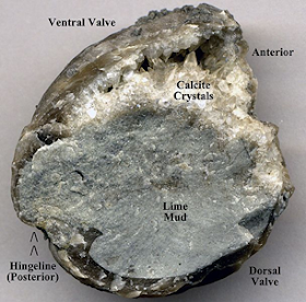
Cavity fills

When an empty space exists in a sedimentary deposit, such as the protected little hollow under a shell, it can be partially filled by sediment. We call this little pocket of space a “void” or a “cavity.” If the cavity is entirely filled with sediment, it’s useless as a geo-petal structure. It only has geo-petal value if it is partially filled in with mud. In fact, this is geo-petal in the strictest sense of the term: it refers to these cavity fillings. Here is how it works: the mud settles under the influence of gravity, lining the bottom of the space (but not the top of the space). Later, as groundwater moves through the sediment, it carries with it dissolved ions, which may bond together, filling the available space with crystals. In the example in Figure 3, the crystals formed are of the mineral calcite, which occurs in a coarse form geologists call “spar.”


Figure 3: In cavity fills, mud fills a portion of the empty space at the bottom and later diagenetic deposition of calcite fills in the remaining empty space (at the top) with spar.

Use this principle to examine the following Figure 4, showing a cross-section through a bed of limestone collected in West Virginia. It has intentionally placed in a vertical position to examine. As you will see, the limestone includes many snail shells (gastropod fossils). A lot of them show this key pattern of infilling with two substrates: gray limy mud and white calcite spar. Note that because the shells are made of calcite also, both the original shell and the subsequent spar appear the same coarse crystalline white:


Figure 4: Geopetal fossils in Limestone.

Which way is depositional “up” in this sample (Figure 4)? You can use the rotation the image to test various orientations, until you get the mud at the (original) bottom and the spar above it in the (original) top of the available space.

Hopefully you determined that the side of the sample next to the pencil was originally “down” (Figure 5).


Figure 5: Image rotation for geo-petal fossils in Limestone.

Quiz X1:

Question:

Is this sample right-side-up or up-side-down? Explain?

Option A:

Right-side-up, since the bottom is filled with mud, and the empty cavity at the top is partially filled with sparry calcite crystals.

Option B:

Up-side-down, since the the bottom is partially filled with sparry calcite crystals, and the top is filled with mud.

Answer:

Right-side-up, since the bottom is filled with mud, and the empty cavity at the top is partially filled with sparry calcite crystals.

Question:

Examine this sample for cavity fills. Which way is depositional "up?"


Option A:

The bottom of the screen (opposite the side where the scale is) is the original depositional "up" direction.

Option B:

The top of the screen (where the scale is) is the original depositional "up" direction.

Option C:

On the left of the screen (where the biggest shells are) is the original depositional "up" direction.

Answer:

The top of the screen (where the scale is) is the original depositional "up" direction.


TO BE CONTINUE....


Mineralogy and Crystallography

  Mineralogy and Crystallography:  Chapter #03 and Chapter #04  A complete pdf is kept in the link mentioned below: Link:  Mineralogy and Cr...